Level Transmitter/Level Switch

Matsushima Measure Tech
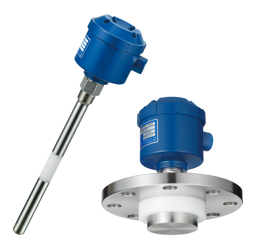
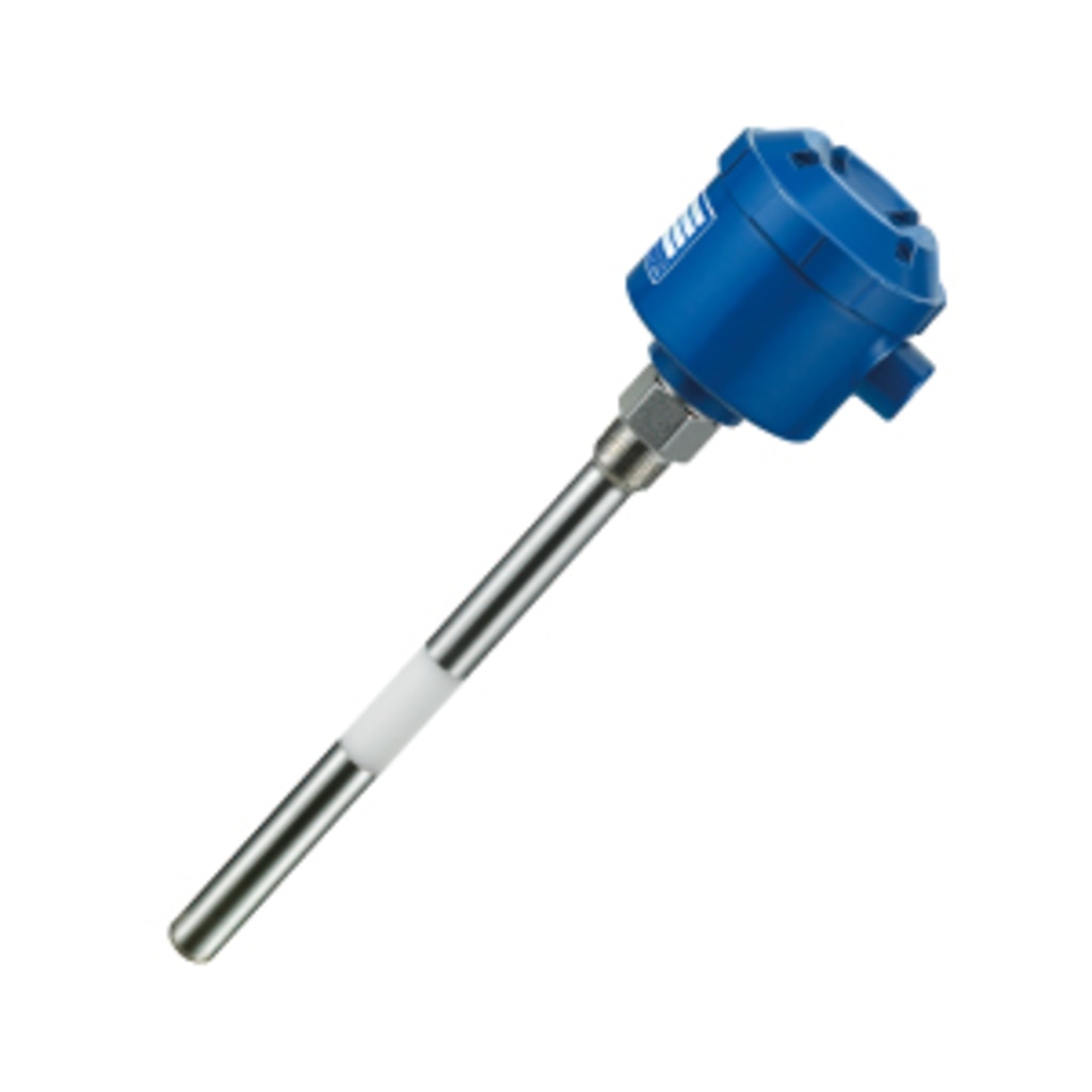
Capacitance level switch is a level switch that detects the presence or absence of an object to be measured by capturing changes in the capacitance between the electrode probe and the tank side wall.
Advantages
- Achieving powder detection at low cost. This level switch is most commonly used for powder detection.
- Since there are no moving parts, it is easy to maintain.
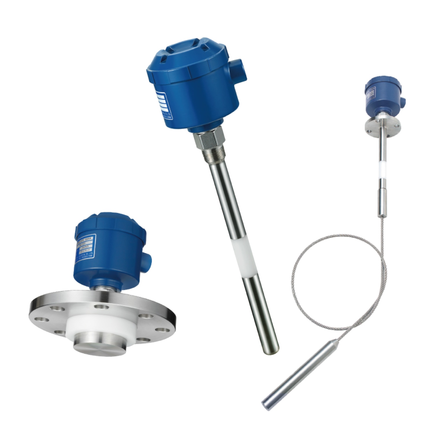
- A large number of electrode types are available to meet various applications.
\ Request for quote /
Features of Capacitance level switch
Liquids, powders, and
various objects can be detected
Appropriate amplifier and electrode selection enables stable detection of many substances. For this reason, we offer a wide variety of electrodes and substrates to meet various measurement objects, applications, and usage conditions.
Suitable for harsh
environments such as
high temperature and
high pressure
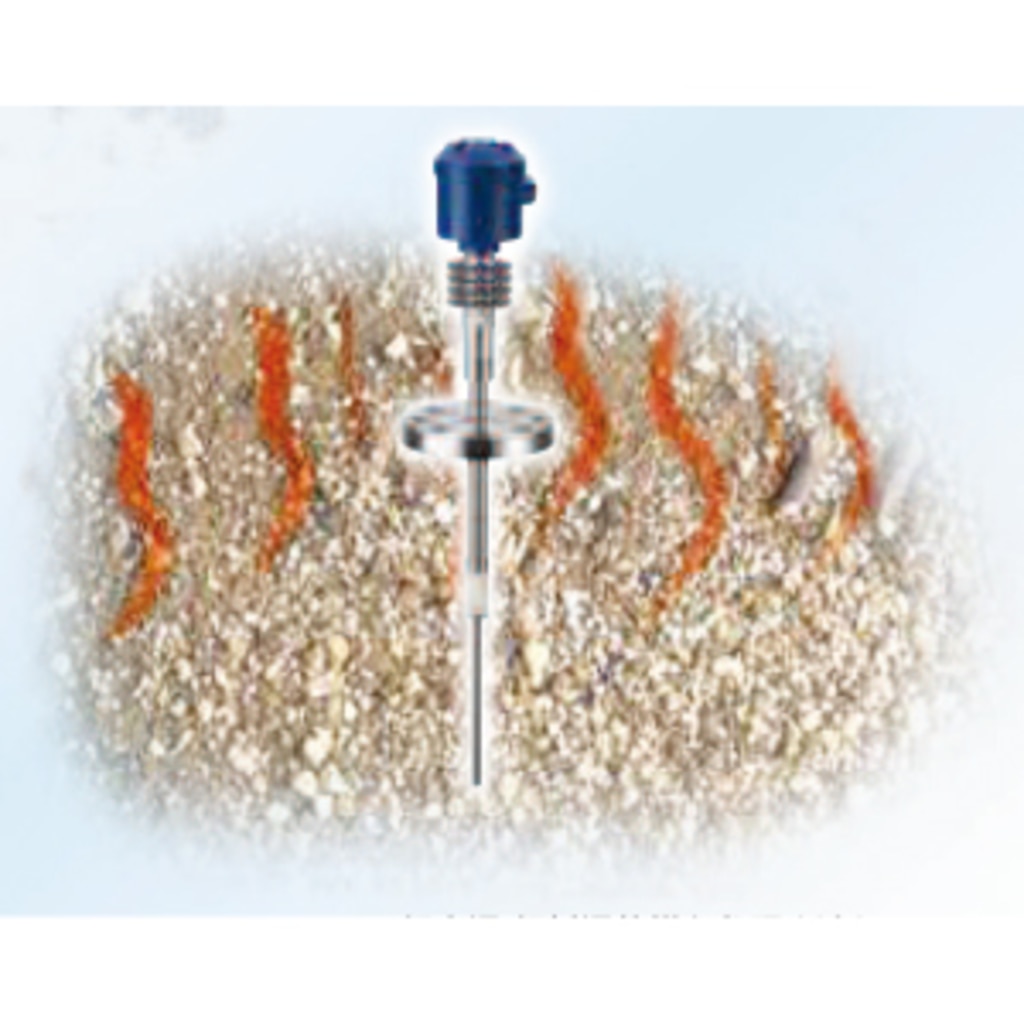
Ultra high temperature of 300℃ or more, ultra low temperature of -200℃ or less, high pressure and vacuum are available. It is ideal for ultra-high temperature processes such as chemical plants and ultra-low temperature processes such as LNG, liquid nitrogen, and liquid hydrogen.
No moving parts,
excellent washability and durability
The probe can be cleaned even if the object to be measured adheres to it.
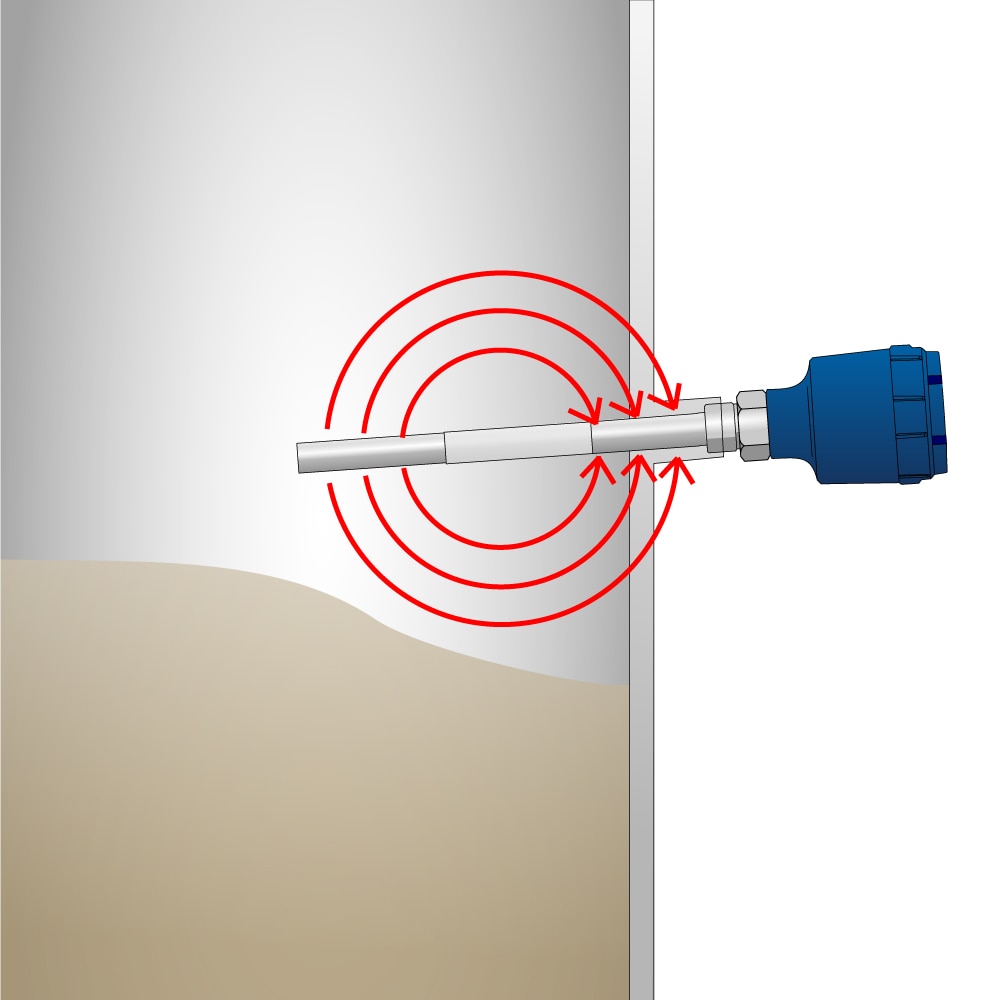
Operating principle
The probe and tank (made of metal) act as electrodes, and the change in capacitance between them is captured and detected.
It detects the change in capacitance value when the space between the electrodes is empty and when it is filled with the object to be measured.
How to use?
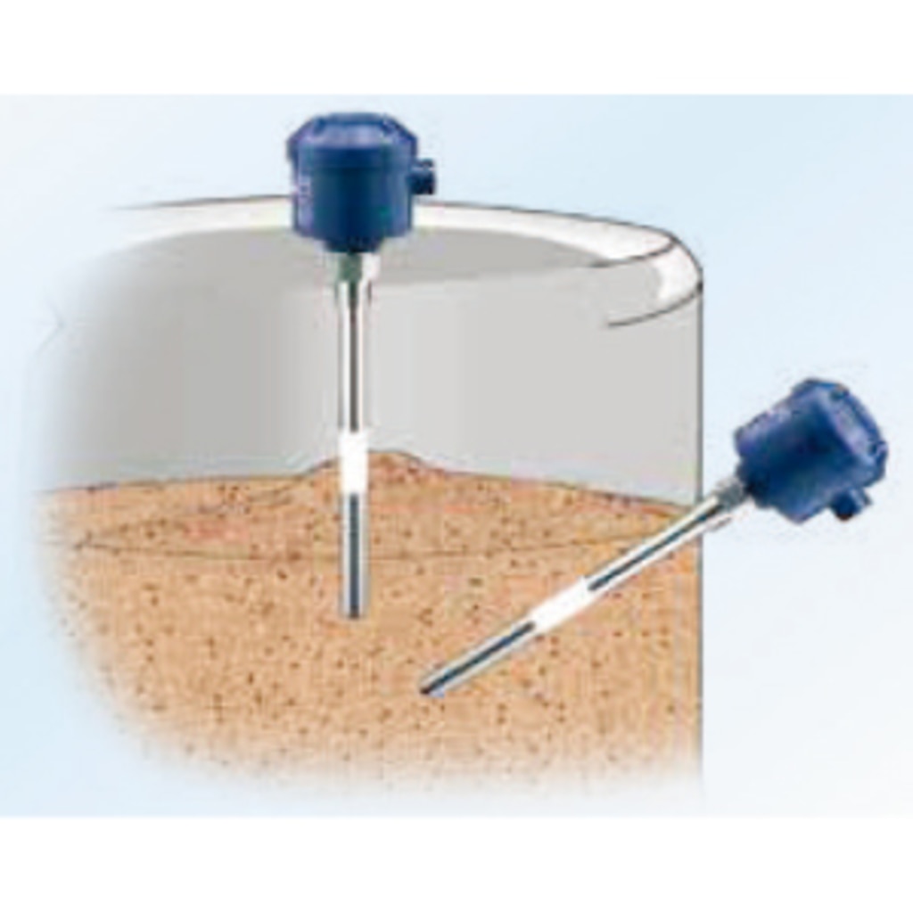
1.Determine
mounting position
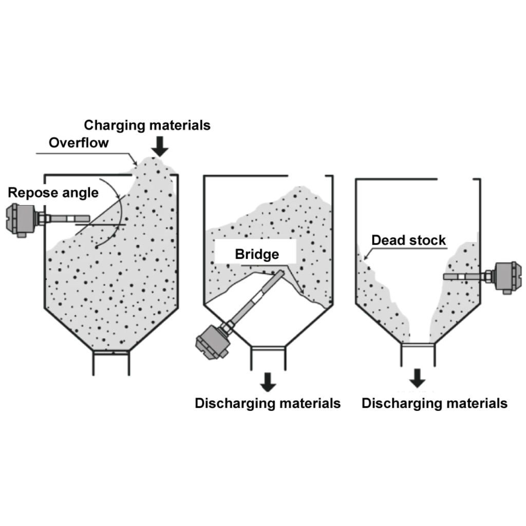
Considering the angle of repose, install the sensor in a location where the object to be measured and the electrode are in proper contact.
Please note that if bridging occurs, the electrodes may be damaged due to malfunction or collapse.
Please note that in dead stock, the object to be measured remains and becomes a detection state.
2. Mounting
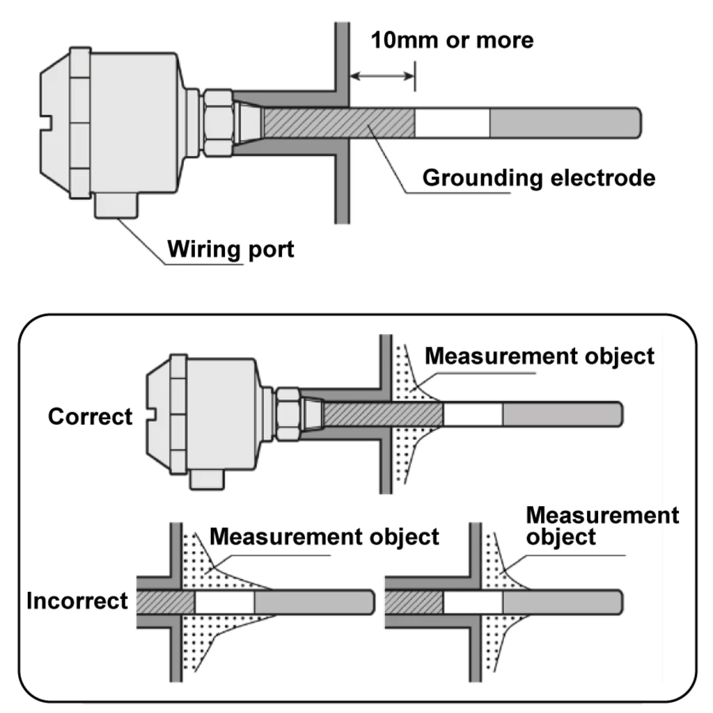
Horizontal/slanted installation (example of integrated type)
Install correctly as shown in the figure, with the wiring port facing downward. As a guideline, the ground electrode should be in the tank by 10 mm or more.
3. Wiring
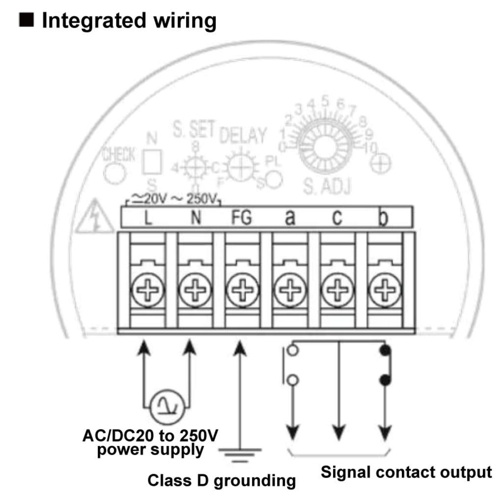
Wire correctly according to the instruction manual. After opening the lid, close the lid tightly to prevent water, dirt, sand, metal pieces, dust, etc. from entering, as it may cause malfunction.
4. Adjustment
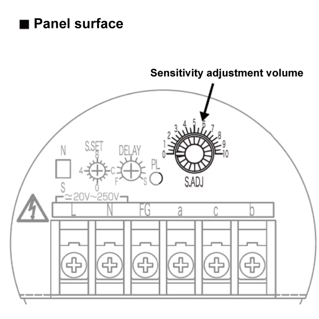
Adjust with the sensitivity adjustment volume. Please note that the adjustment method differs depending on the unit/amplifier you are using.
*For details, please refer to the instruction manual.
\ Request for quote /
Please feel free to ask us if you have any questions
or you want our support. ⇩⇩⇩
Please feel free to contact us if you have any inquiries.
Click here to download documents.


© Matsushima Measure Tech Co., Ltd.