Level Transmitter/Level Switch <Powder>

Matsushima Measure Tech
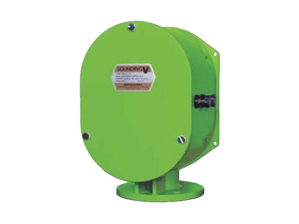
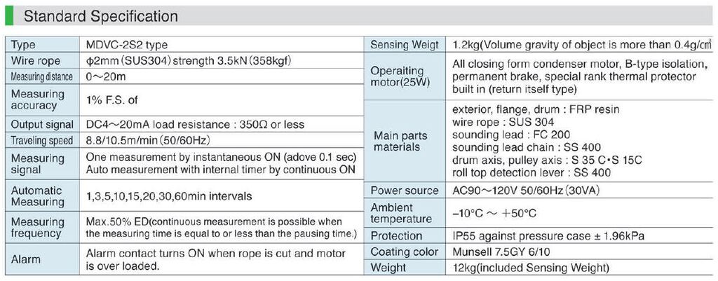
Sounding V is an inexpensive, compact and lightweight contact-type level transmitter that integrates a sensor and converter. It is widely used in grain and feed silos.
Advantates
- Just plug in the power and set 0%-100% and you're ready to go.
- Achieves continuous level measurement at the cost of several level switches.
- Using weights to physically sense the object to be measured is close to the feeling of measuring it by hand, so you can feel its certainty.
\ Download or Request for quote /
Features of Sounding V
The main features of Sounding V are:
Not affected
by dust or gas
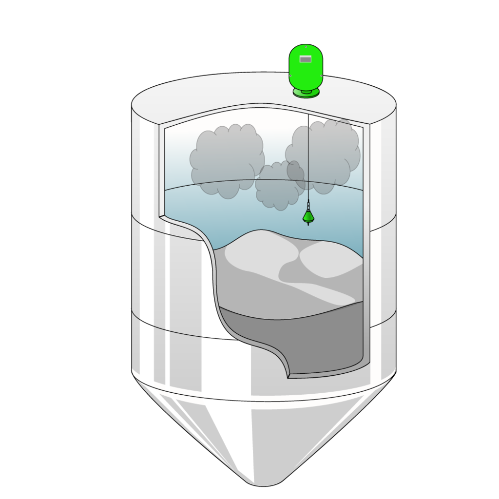
Since weights with mass are used for measurement, they are not affected by dust or gas.
Ready to start
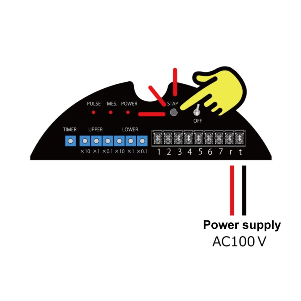
Measurement can be started immediately by turning on the AC100V power supply and pressing the measurement switch.
Use durable wire rope

A wire rope made of SUS304 with a thickness of 2 mm is used. The breaking strength of the wire rope is 1200N (122kgf) or more, which is a reliable strength.
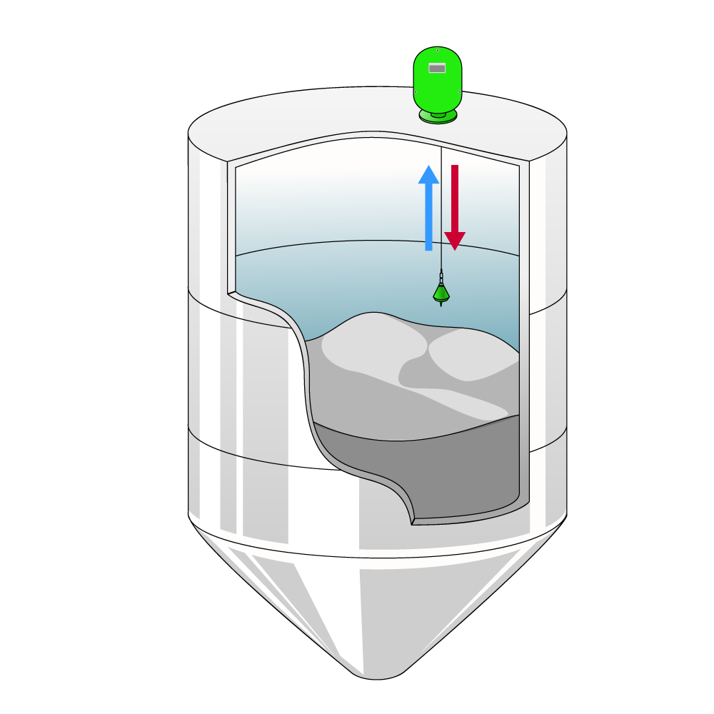
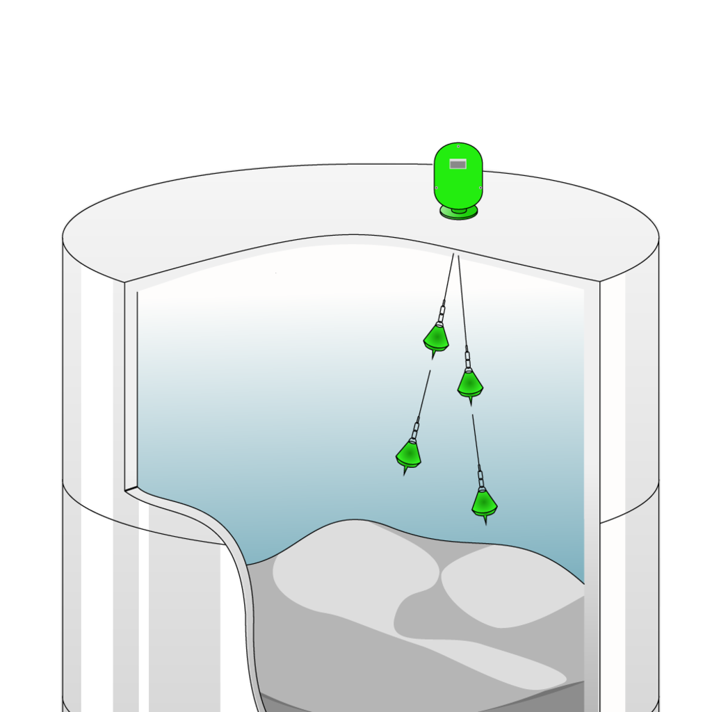
Operating principle
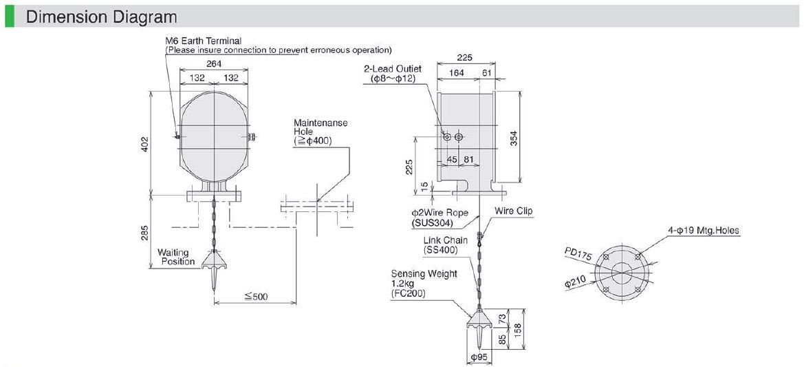
When the sounding automatically winds down the sensing weight attached to the tip of the wire rope, the weight lands on the object and automatically winds it up. By measuring the length of the rope while this weight winds down, the material level of the silo or tank can be measured.
※動画の製品はサウンジングM'sになります。
How to use?
1.Determine the mounting position
Choose a position where no obstacles will enter the measurement area of the Sounding V, and where no objects will enter the dead zone of the Sounding V. When measuring, the weight swings up and down like a pendulum, so keep the weight away from the wall while considering the swing. If you have any concerns about the mounting position, please contact us.
2. Mounting
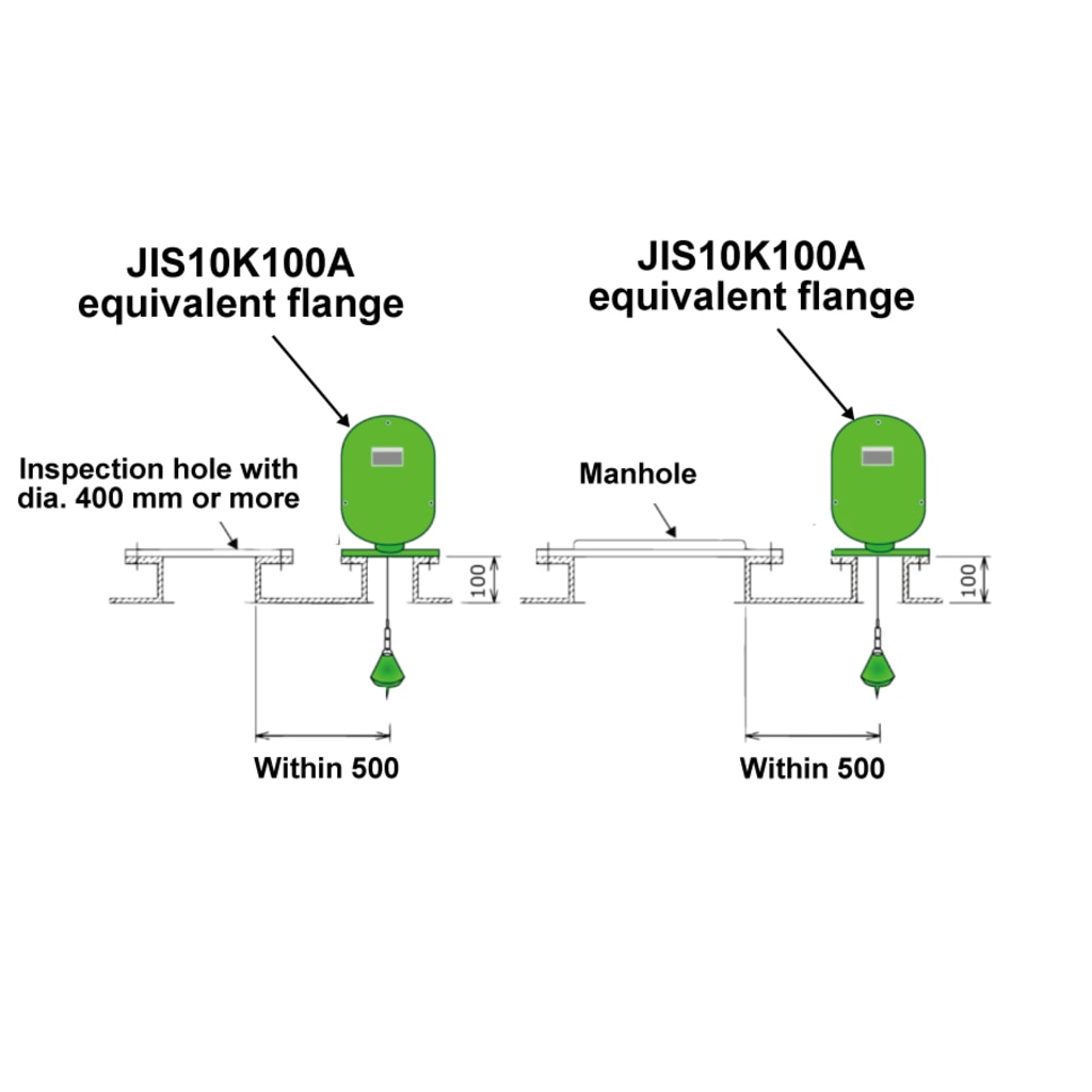
When installing, secure an inspection space around the Sounding V. Make sure the wire rope is not detached from the drum or pulley. When using a weight that is larger than the flange mounting opening size, provide an inspection window that is larger than the weight size. It is required for weight mounting and removal.
3. Wiring
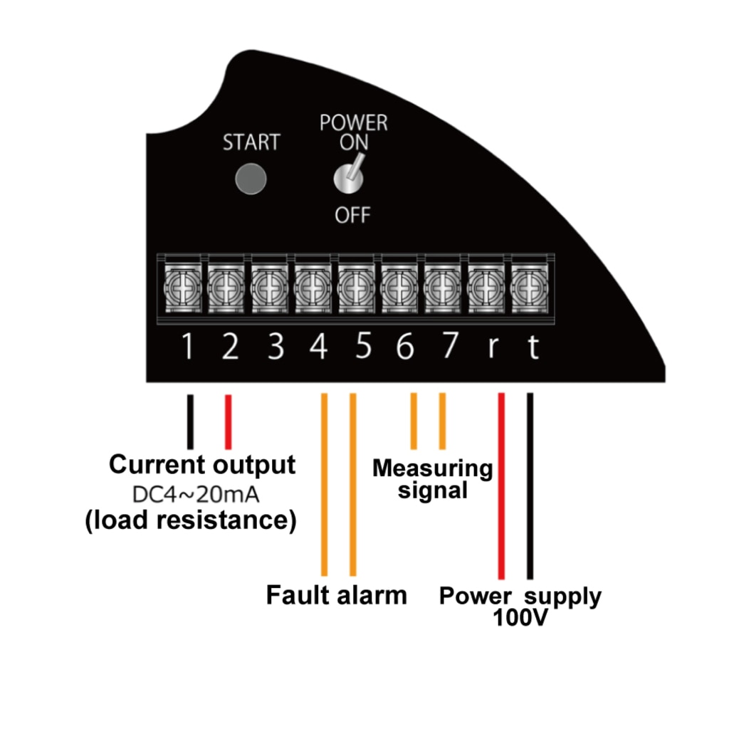
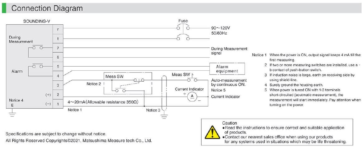
Wire the power supply, analog output, and fault alarm contact. Measurement starts when the power is turned on.
4. Adjustment
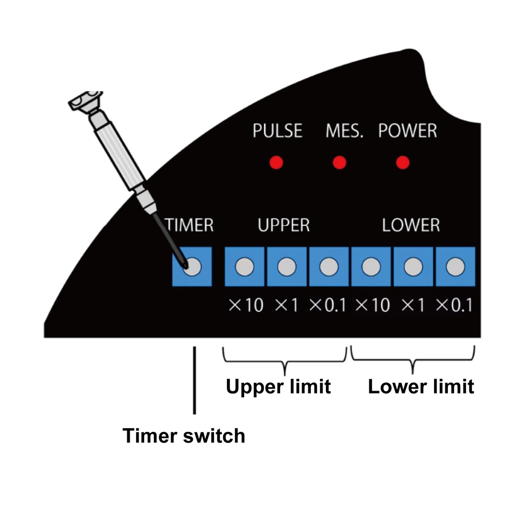
Complete with 0% and 100% settings and automatic timer settings. Please refer to the instruction manual for details.
*For details, please refer to the instruction manual.
\ Down load or Request for quote /
Model lineup
\ Download or Request for quote /
Please feel free to ask us if you have any questions
or you want our support. ⇩⇩⇩
Please feel free to contact us if you have any inquiries.
Click here to download documents.


© Matsushima Measure Tech Co., Ltd.