
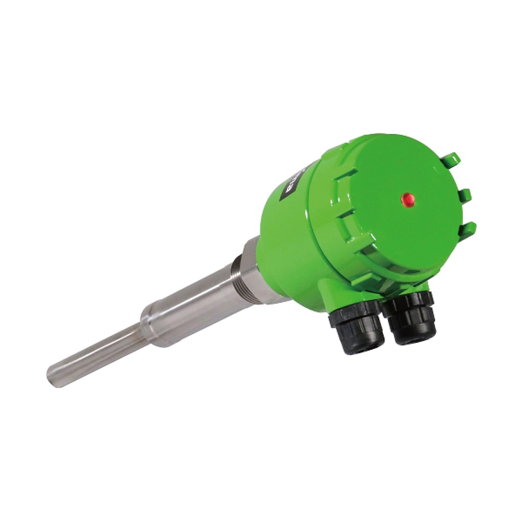
Level Transmitter/Level Switch <Powder>

Matsushima Measure Tech
Vibrating level switch is an excellent level switch for detecting substances with low specific gravity and low dielectric constant.
Advantages
- Can detect objects with low specific gravity (light weight). It is suitable for objects to be measured that are idled by the paddle switch.
- Can detect objects with low relative permittivity. It is suitable for objects with a low dielectric constant that are difficult to adjust with a capacitive level switch.
\ Download or Request for quote /
Features of Vibrating level switch
The main features of the vibrating level switch are as follows.
Detects ultralight
fine powder!
It can be used for a wide range of applications, from extremely light fine powders with a bulk specific gravity of 0.02 g/cm3 to granular materials such as grains.
Not affected by electrical characteristics
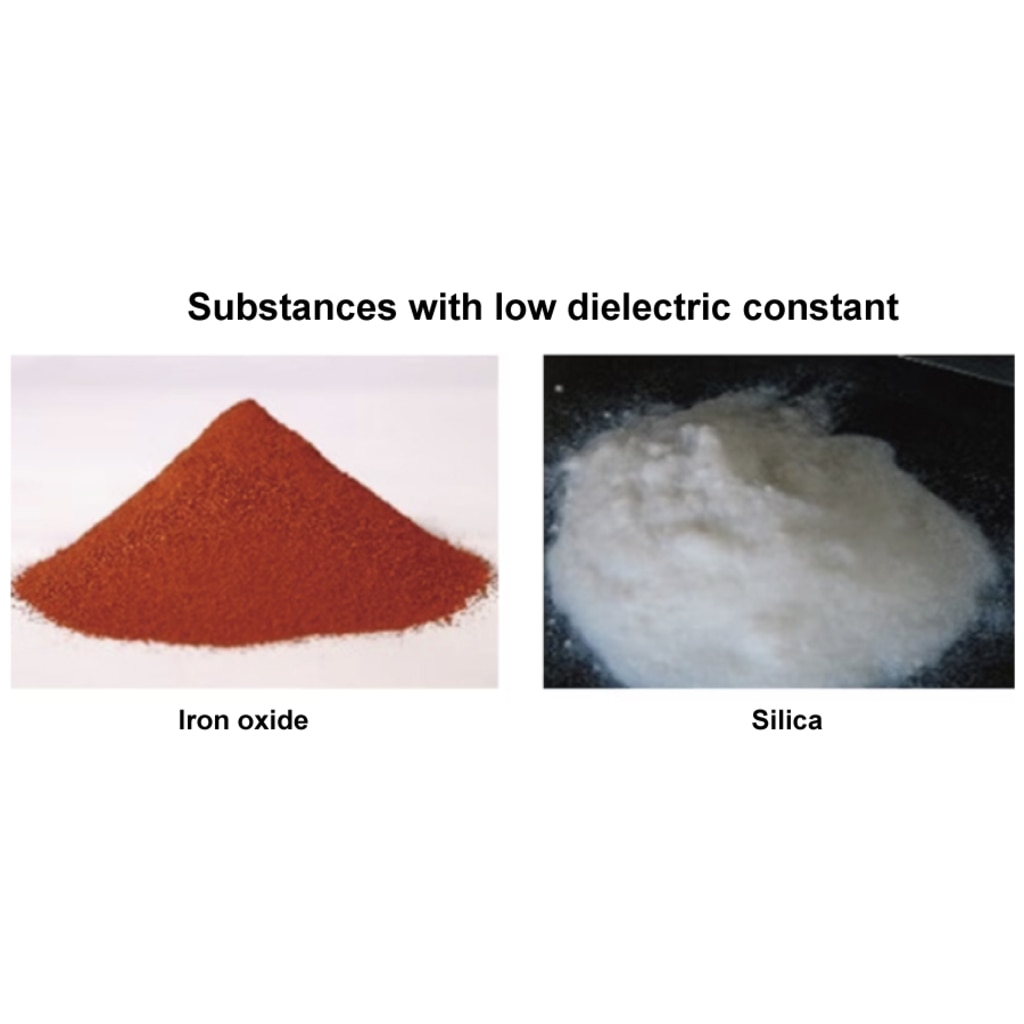
Due to the principle of operation, it is not affected by electrical properties such as relative permittivity and conductivity of the object being measured.
Five functions that
emphasize
on-site usability

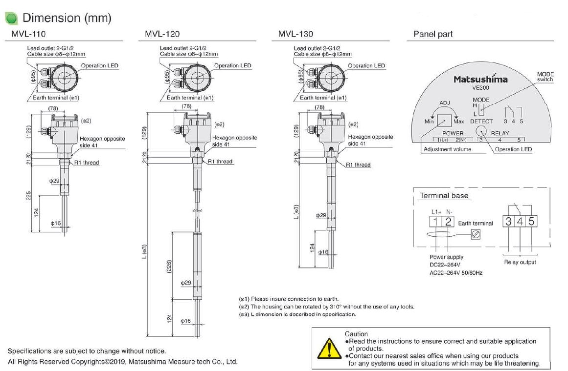
- Two-color LED operation indicator that can be seen from the outside
- Screw-up type terminal block that screws do not fall off
- 310° swivel housing for easy wiring
- Detection operation switching according to upper/lower limit setting
- free power supply.
AC/DC22~264V 50/60Hz
Please see the catalog for details.
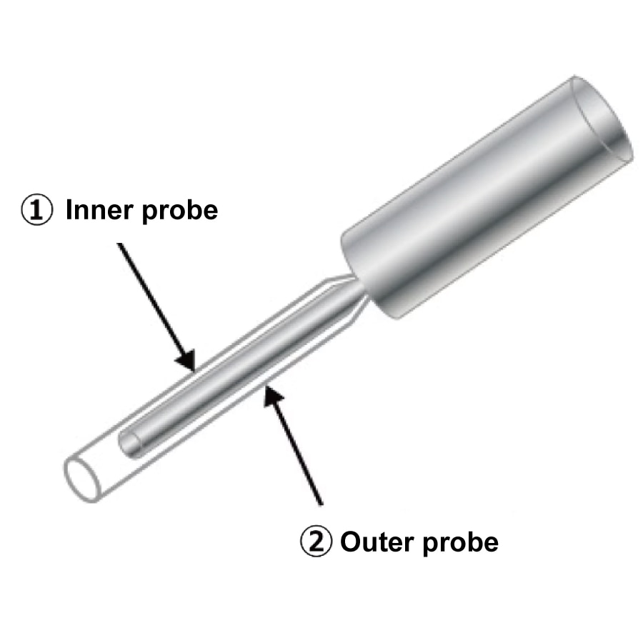
Operating principle
The detection probe of the vibrating level switch has a dual structure of an inner probe and an outer probe. When the inner probe is slightly vibrated at a certain frequency by a piezoelectric element, the outer probe resonates. Resonance is greatly reduced by burying the outer probe in the stored material, and the change is captured and detected.
How to use?
1.Determine the
mounting position
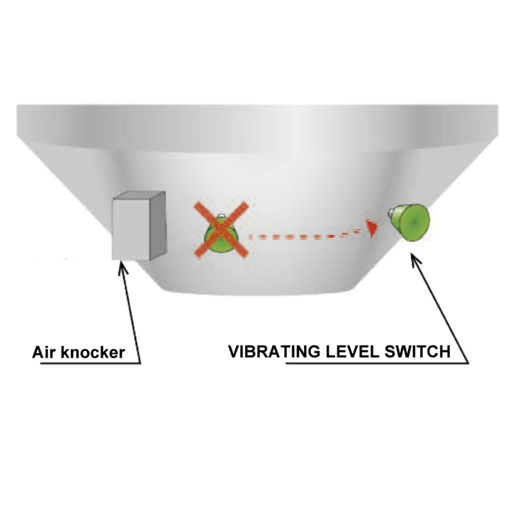
Mounts to ceiling or tank sidewall. Avoid installing near sources of intense vibration such as knockers, which may cause malfunction or false detection . If you have any concerns about the mounting position, please contact us.
2. Mounting
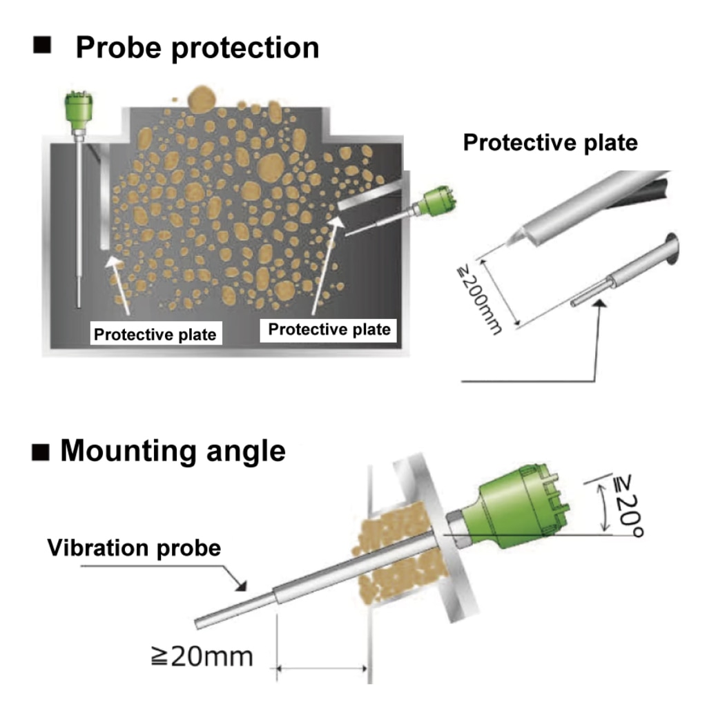
Avoid direct contact with the electrode while it is being charged, as this may cause damage. It is effective to attach a protection plate. Also, when installing on the lower side wall, tilting the probe by 20° or more can reduce the load on the probe.
3. Wiring
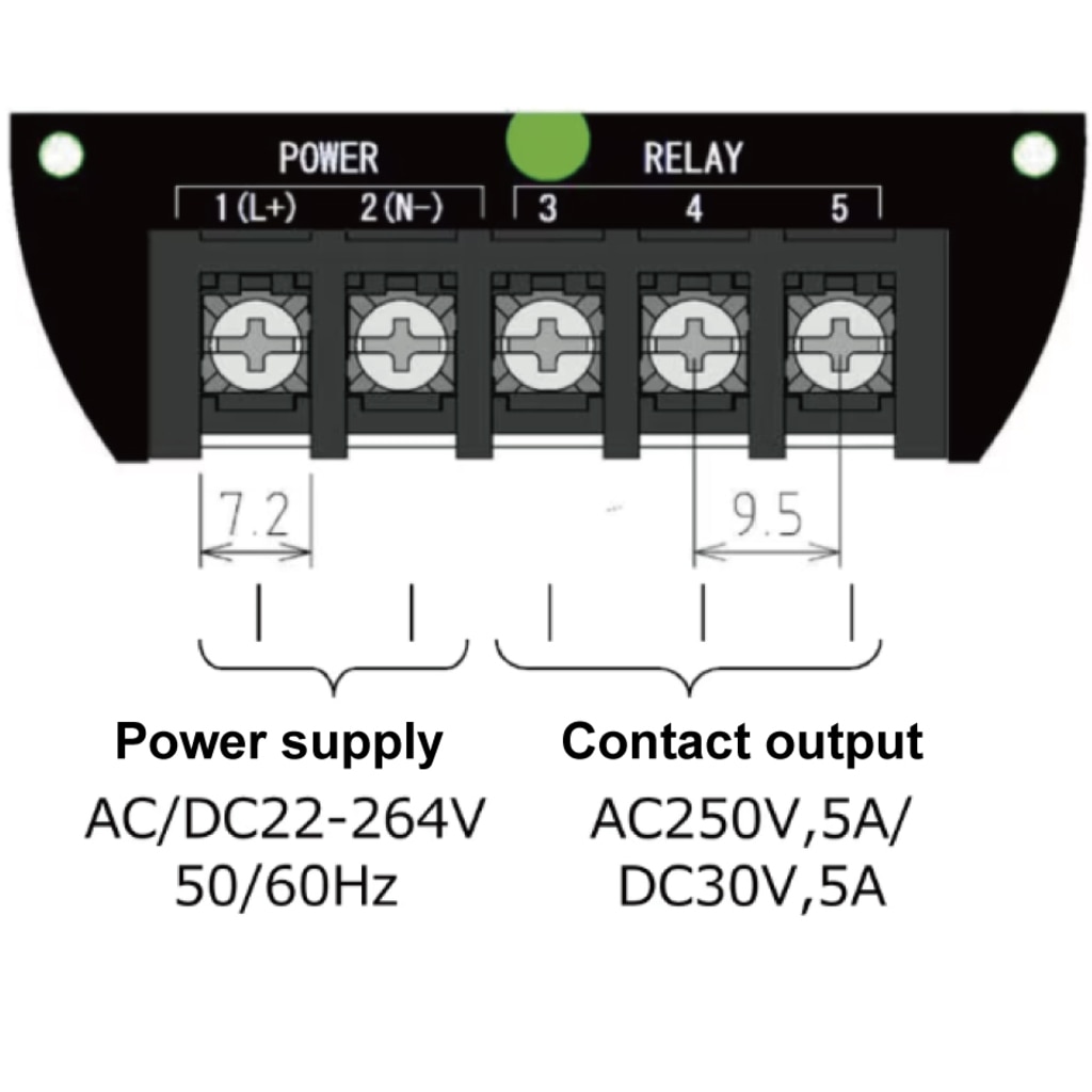
The power supply is a free power supply and supports AC/DC22~264V 50/60Hz. The output signal is SPDT and the contact capacity is AC250V, 5A/DC30V, 5A.
4. Adjustment
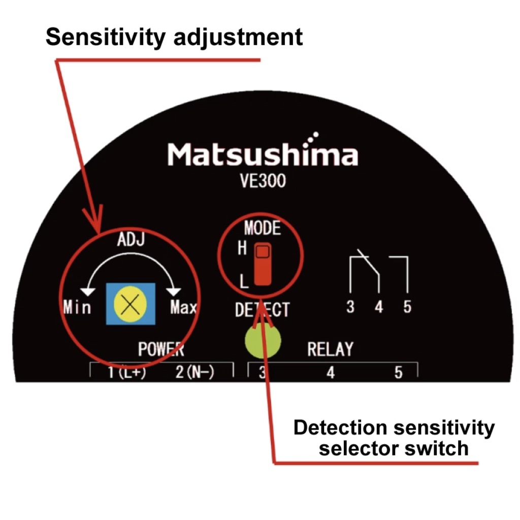
Sensitivity adjustment is only sensitivity adjustment by volume.
Next, by setting the detection operation selector switch, it is possible to set contact output operation for upper and lower limits and lamp display.
*For details, please refer to the instruction manual.
\ Download or Request for quote /
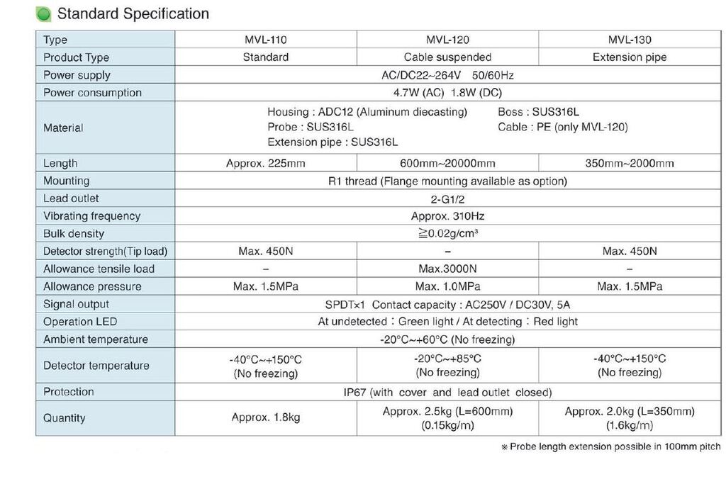
Model lineup
\ Download or Request for quote /
Please feel free to ask us if you have any questions
or you want our support. ⇩⇩⇩
Please feel free to contact us if you have any inquiries.
Click here to download documents.


© Matsushima Measure Tech Co., Ltd.